-
Exhaust System Noise Reduction Using Quarter Wave Tube (part 3 of 4)
Last week we looked at how we used different variations of filters for frequency analysis and the effects of additional sound pressure levels. Click here to see last weeks post.
Method:
Equipment and set-up
A CEL-254 sound level meter was used to record the overall SPL in dB(A) for each test. This also acted as the microphone input to the different frequency band however it should be noted that the dB levels shown in the software screenshots do not relate to the actual levels recorded by the sound level meter.
This was because the microphone input had not been fully calibrated.
The software was installed on an acer travelmate C300 laptop computer with an intel 1.6 Hz processor and512MB RAM. The microphone was placed 0.5m away from the near side tailpipe outlet in the horizontal plane at an angle of 45 degrees to the exhaust flow.Initial Measurements
The first stage of the development process was to perform an initial analysis on the existing exhaust system in order to identify the characteristics of the noise that might be contributing to the excessive levels.
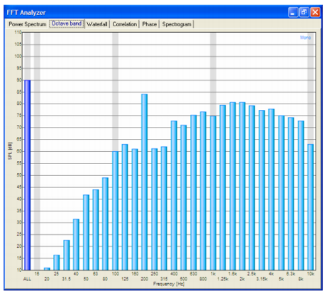
A one third octave analysis was performed on the vehicle with the engine speed held briefly at 6000 rpm. The results are shown to the left.
The results show a distinct peak at the 200 Hz band. This relates to the second Harmonic of the engine rotation frequency at 6000 rpm. The second Harmonic is stronger because there are two firing events per revolution. This dominant firing frequency is typical of typical of naturally aspired engines with tuned exhaust manifolds and straight through systems, where the even firing pulses are transmitted, with very little interruption, to the end of the system.Initial Measurements
The first stage of the development process was to perform an initial analysis on the existing exhaust system in order to identify the characteristics of the noise that might be contributing to the excessive levels.
A one third octave analysis was performed on the vehicle with the engine speed held briefly at 6000 rpm. The results are as shown below.The results show a distinct peak at the 200 Hz band. This relates to the second Harmonic of the engine rotation frequency at 6000 rpm. The second Harmonic is stronger because there are two firing events per revolution. This dominant firing frequency is typical of typical of naturally aspired engines with tuned exhaust manifolds and straight through systems, where the even firing pulses are transmitted, with very little interruption, to the end of the system.
APPLICATION OF THEORY
The decibel addition rule shows that if the higher frequency BPLs were reduced but the 200 Hz BPL remained unchanged, there would be little difference in the overall SPL. Therefore in order to reduce the overall SPL, it is necessary to maintain or reduce the BPL of the higher frequency brands while also significantly reducing the BPL of the 200 Hz band. As size and weight are key criteria for this application,it would not be suitable to simply introduce bigger silencers with more absorption material, a typical approach to noise attenuation. Redirecting the flow within the existing silencers may help you to break up the dominant frequency: however this is likely to result in reduced volume available for absorption material.
Experience has shown that this can have a negative effect by reducing the generally high level of broad-band attenuation that the material provides. It was therefore decided to attempt to maintain the volume of absorption material of the existing system in order to maintain the low BPLs for the higher frequencies. Further to this it would be necessary to specifically target the 200 Hz frequency to reduce the BPL, with the aim of reducing the overall SPL.
The selected method for targeting the specific frequency was a quarter wave tube (QWT). this device is essentially a side branch attached to the exhaust system that has an overall length equal to a quarter of the wavelength of the specific frequency in question. The theory suggests that a sound wave entering the side branch will travel to the end of the tube where it is reflected back to the branch opening. By the time the wave has traveled a quarter wavelength down the tube and a quarter wavelength back again, the wave will be a total of half a wavelength (or 180 Degrees) out of phase. In simple terms, the wave approaching from the exhaust system and the wave coming back back from the QWT will cancel each other. In reality, a complete cancellation of the wavesAPPLICATION OF THEORY
An Initial calculation was performed to obtain a value for the wavelength of the 200Hz frequency.
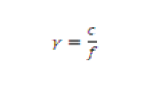
Where Wavelength (m), c = Speed of Sound (ms-1), f = Frequency (Hz). From this, the length of the required QWT could be determined. Note that the speed of sound is dependent upon gas temperature, an exact value for which was not known during the initial stages of the development. Therefore the QWT length determined was used as a starting point for physical testing.
Next week we will look at the results and conclusion from our work and a general summary of the case.
This blog post is taken from our whitepaper ‘Noise Reduction Using quarter wave tube’. Download the full length whitepaper (click here).
- T +44 (0) 1327 261797
- E sales@btbexhausts.co.uk