-
How to Improve Performance, Efficiency, and Lightweighting - A study of Exhaust System Back Pressure
This is one of a series of articles that examine how BTB can find performance advantages through the exploitation of greater efficiency, and these are some of the challenges that we have overcome in our past which will provide the background for uncovering the solutions that will shape our future.
The effect back pressure has on engine performance?
In the context of high performance exhaust system design, back pressure is often referred to as a critical measure of improvement. So:
- What is back pressure
- How is it measured
- What effect does it have on engine performance?
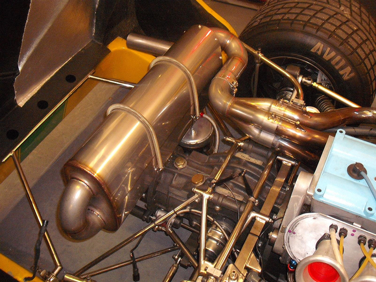
Back pressure is the pressure that is measured inside the exhaust system usually between the engine and the final silencer. It is expressed as the pressure above atmospheric pressure in units such as psi (lbs/sqin), mbar, Kpa, etc. It is caused as the hot exhaust gases exiting the engine are forced down the exhaust pipe and silencers by the act of combustion and the pumping action of the pistons on the exhaust stroke of the cycle. The size of the exhaust pipe, the type, number and radius of any bends, any restrictions caused by silencers (mufflers) and catalytic converters all contribute to the back pressure.
Back pressure constitutes one of the parasitic losses inherent in the internal combustion process referred to as the pumping loss. This is the energy wasted by the engine due to the effort required to pump the waste gasses away from the engine and down the exhaust pipe.
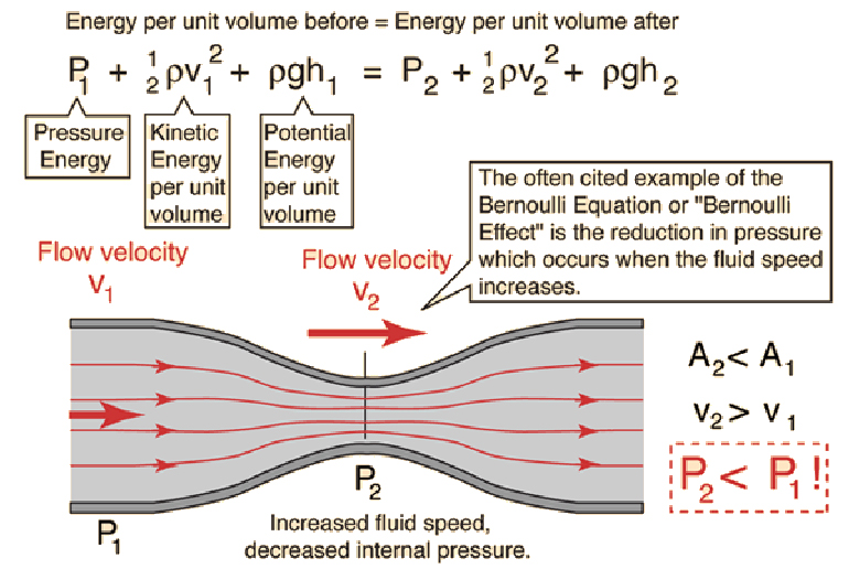
Back pressure should always be considered with reference to gas velocity. If minimal back pressure is key to engine efficiency, why not just run the biggest exhaust pipe possible to the back of the car? According to Bernoulli’s theory, as gas velocity increases so pressure reduces. Too large a pipe for a given gas flow, and velocity drops which also increases the likelihood of turbulent non- laminar flow. In normally aspirated engines, where tuning of the sound wave pressure pulses is key to combustion chamber efficiency, the location of pressure nodes can adversely affect consistent generation of standing waves in the pipe.
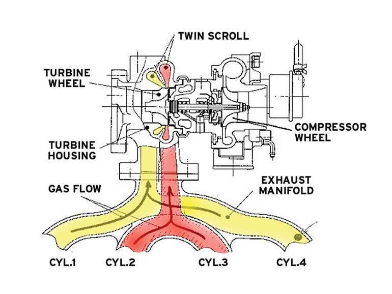
Back pressure and turbo charged engines
Turbo charged engines produce even greater flow of gases, which require large pipes and a lower back pressure in the exhaust will help to drive the turbine faster due to the pressure drop between the manifold (before the turbine) and the exhaust system (after the turbine). The turbine itself prevents any reverse pressure pulses in the downstream system having any effect on the combustion chamber efficiency. Insertion loss, is the term used describe the effect that each element of the exhaust system has on the total pumping loss. Therefore, adding an extra silencer would create an insertion loss equivalent to the change in back pressure caused by its addition.
The three main silencer types
The three main silencer types can be described as absorptive, reactive and reflective.
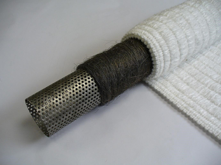
The absorption silencer
An absorption silencer has a perforated tube that runs through a volume that is packed with sound absorbing fibrous material such as mineral or glass-fibre wool. The sound energy is dissipated by converting the vibrations into heat. A reactive silencing element is a resonating chamber or tube adjacent to the flow of exhaust gas that is tuned to cancel certain frequencies generated by the exhaust pulses.
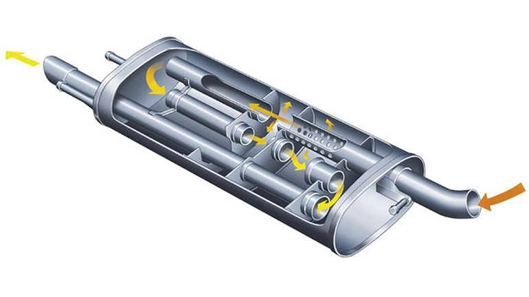
The reflective silencer
A reflective silencer sets up waveforms in the flow of gasses that are reflected by its internal baffles
which cancel incoming waveforms. These tend to be the most restrictive to flow and therefore have the greatest insertion loss. Restrictive silencers can often be blamed for lack of performance, but the following data trace illustrates that with careful design performance losses can be minimised. The data shows the difference in maximum speed measured on a sports racing car at the fastest point on the Hanger straight at Silverstone GP circuit. The only noticeable difference is that with the quieter silencer fitted the throttle is at 102%, so perhaps the driver was pressing harder on the pedal because it didn’t sound as fast!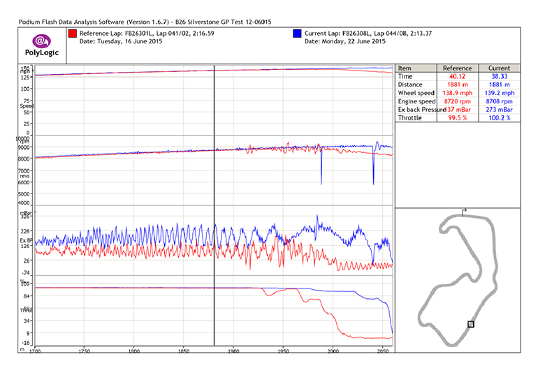
Exhaust system bends
The bends in an exhaust system also constitute insertion losses, especially if they are not formed in a way that maximises cross sectional area and helps to maintain laminar flow. Mass produced exhaust systems sometimes use compression or press bends which reduce the cross sectional area and distort the smooth walls of the exhaust pipe. Mandrel formed bends maintain a much more uniform cross section and are therefore most commonly specified for high flowing performance exhausts.
The radius of the bends should be the maximum possible that will fit within the constraints of the exhaust packaging envelope. If non-round sections are required, the equivalent diameter equations relevant to elliptical or oval ducting should be considered to avoid unnecessary restrictions in flow.Catalytic converters
Catalytic converters are now a fundamental part of an exhaust system, and are mandatory in most forms of motorsport featuring production based cars. The design of the cone shape into and out of a catalytic element is critical to good flow distribution across the cells of the cat for efficient catalytic function and minimum back pressure. Sometimes compromises are made to the cone shape and its axial symmetry to speed the light-off time of the cat. This is particularly common with close coupled cats that are positioned in the exhaust manifolds or very close to the engine.
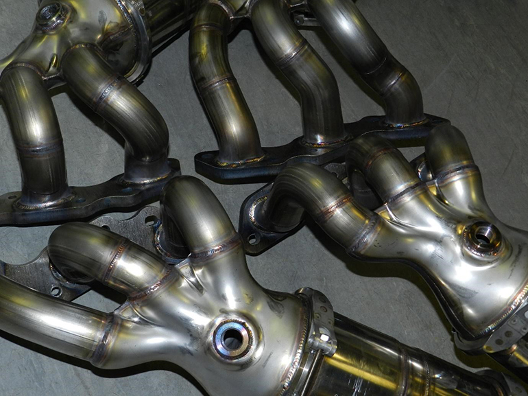
A performance orientated, or motorsport cat will feature long and sometimes parabolic tapered cones, to maintain laminar flow. These can also serve to function as a pulse generator to improve the tuning potential of equal length manifolds.
Read the report on the optimisation of a catalytic converter cone design using Computational Fluid Dynamics simulation: Click here to access to full report

Pictures/Illustrations:
- V12 collectors CFD developed for optimum Catalyst flow distribution
- FIA Cats
- Marcos cat cones Advantage CFD paper, click here to access the report
- Back pressure vs V-max - Thanks to Andrew Schryver for sharing his data
- T +44 (0) 1327 261797
- E sales@btbexhausts.co.uk